Planetary Robotics 3D Viewer

Explore planetary surfaces in full resolution.

PRo3D is an interactive 3D visualization tool that allows planetary scientists to work with high-resolution 3D reconstructions — from orbiter and rover cameras, at the accuracy of the original data.

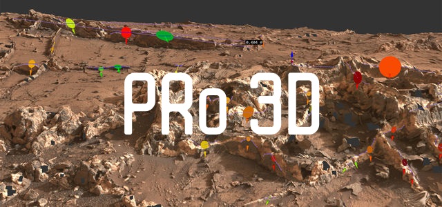
The PRo3D logo over a 3D reconstruction of a Martian outcrop annotated with coloured measurement markers.

Who uses PRo3D?

PRo3D aims to support planetary scientists by exploring high-resolution 3D surface reconstructions from orbiter and rover cameras. In the scope of ESA and NASA missions, new features are developed to support the mission.

Features

Built for real geological work

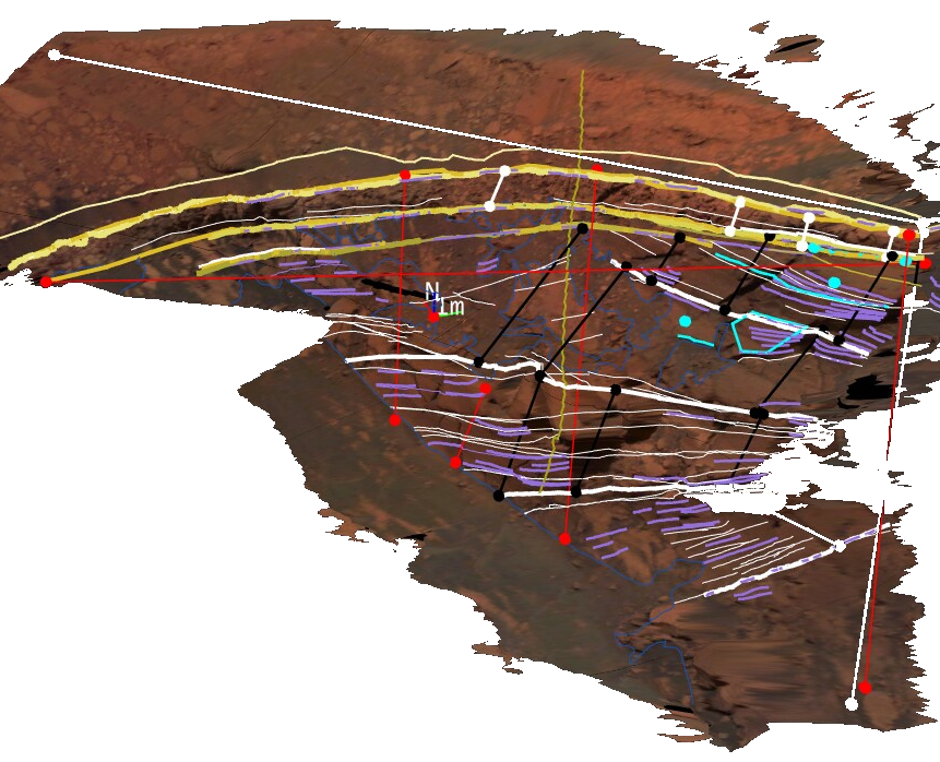
A 3D outcrop model overlaid with point, line and polyline annotations in several colours, plus a dip-and-strike orientation marker.
01

Geological Annotations

PRo3D lets users pick points on the 3D surface at the full resolution of the data present. Our tools contain point, line, polyline and ellipse annotations, while line segments are projected onto the surface. Various measurements are computed at the highest possible accuracy, such as the distance along a 3D surface (waylength) or dip-and-strike orientations of sediment structures.

  • Various annotation types
  • Measurements and computations based on annotations
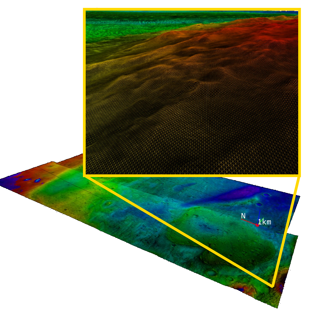
A colour-coded elevation map of a large Martian region, with a zoomed inset revealing the dense triangle mesh beneath the surface.
02

Large Data

Surface reconstructions from high-resolution satellite images can easily yield gigabytes of data in terms of geometry, imagery, and additional layers. With PRo3D users can explore huge datasets interactively and even perform measurements of topographic features.

The displayed dataset consists of 2 GB of raw 3D position vectors, a 1 GB elevation map, and 10 GB of image data — rendered at interactive framerates with commodity hardware, utilizing adjustable level-of-detail and out-of-core techniques.

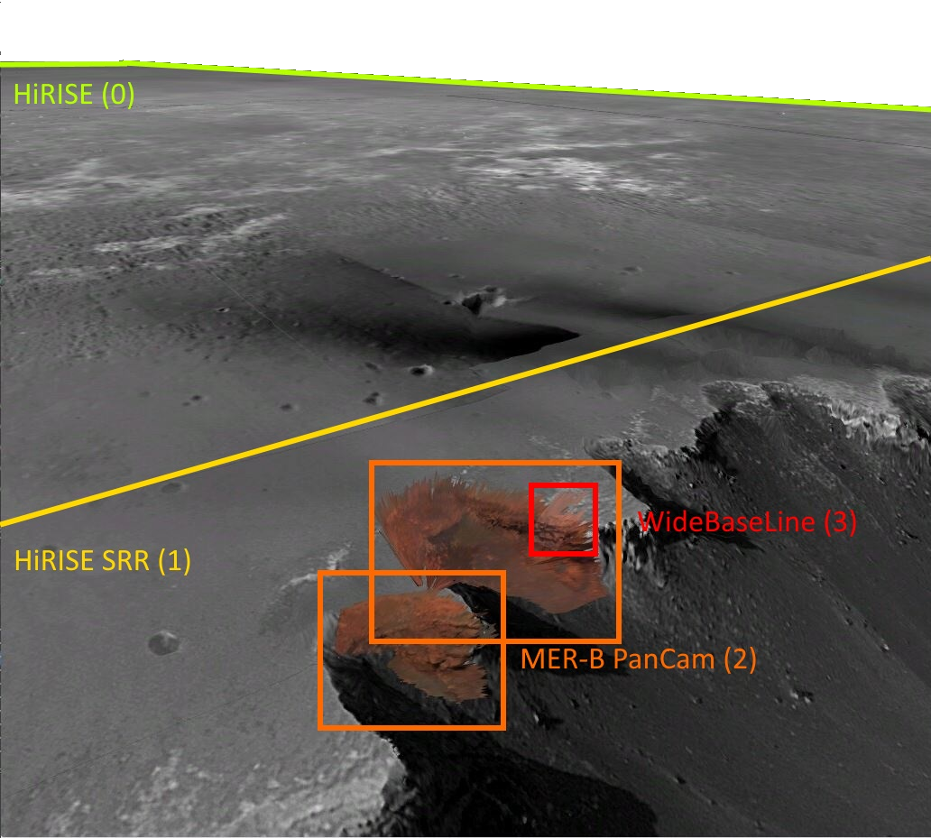
Victoria Crater rendered from four overlapping reconstructions — HiRISE, HiRISE SRR, MER-B PanCam and WideBaseLine — each outlined in a different colour.
03

3D Layers

Although PRo3D is not a GIS system, we need to provide our users with typical GIS features to solve their geospatial problems, such as evaluating topographic or geological features.

Our 3D layering technique allows a seamless integration of different reconstructions present at a single location. Unlike image or DTM layering, we allow users to blend full 3D data by assigning rendering priorities — which is crucial to explore reconstructions from multiple rover camera instruments.

  • Rendering priorities
  • Multi-instrument blending

Data

Formats & provenance

Currently, PRo3D supports OBJ files but works best with reconstructions in the proprietary data format OPC (Ordered Point Clouds), basically consisting of hierarchically organized surface patches. These reconstructions stem from orbiter images and rover images and are produced by Joanneum Research by using the PRoViP processing pipeline.

Many surface reconstructions have been generated from, for instance, the HiRISE, MER-A, MER-B and MSL missions from various instruments. An ongoing project evaluates terrestrial applicability of PRo3D and the PRoViP pipeline by capturing outcrops in the UK. Two example datasets are provided below.

Getting started

Up and running in three steps

  1. 1

    Download PRo3D

    Grab the latest stable build from our release page.

    Release page
  2. 2

    Download a dataset

    Pick one of our example reconstructions to open in the viewer.

  3. 3

    Launch the viewer

    Unpack the archive and start the executable.

    PRo3DViewer.zip → PRo3D.Viewer.exe

PRo3D is also available in source code form on GitHub. If you have questions on how to use PRo3D or want to contribute, please feel free to join our Discord channel.
Subscribe to our mailing list at pro3d+subscribe@lists.vrvis.at to stay up to date with our newest features and releases - just send us the pre-filled mail and reply to the confirmation that you will receive.

Academic or commercial inquiries — science@vrvis.at PRoViP & other reconstructions — gerhard.paar@joanneum.at

Citation

Using PRo3D in your research?

If you have used PRo3D in your research and would like to cite it in your publications, please use the following reference and DOI for PRo3D:

Barnes, R., Gupta, S., Traxler, C., Ortner, T., Bauer, A., Hesina, G., et al. (2018). Geological analysis of Martian rover-derived Digital Outcrop Models using the 3-D visualization tool, Planetary Robotics 3-D Viewer — PRo3D. Earth and Space Science, 5, 285–307.

If you would prefer to cite the software in an acknowledgement rather than the references section, that is also fine with us. We suggest a statement like:

“This research made use of PRo3D, a 3D viewer for exploration and geologic interpretations of planetary surface reconstructions (https://doi.org/10.5281/zenodo.6674707).”

The most important thing is the inclusion of the Zenodo DOI link, which is what makes it possible for us to track the impact of PRo3D. Citations to our software are very helpful to us for professional advancement, securing funding, justifying expenses to project sponsors, etc. — exactly like citations to traditional research publications.

Tutorials

Learn PRo3D

Five short screen recordings that take you from an empty viewer to measured annotations on a Martian outcrop. The clips have no narration — follow the description next to each one.

  1. 010:28

    Importing OPCs

    At first we want to add a surface to our 3D scene. Open the menu and click Surfaces → Import OPCs, which opens a folder browser dialog. A surface folder contains one or more OPC folders. Select the surfaces you want to add and confirm by clicking Select Folder.

    If you get lost in the black void of 3D space, just click to find your surfaces again. If you are not sure what an OPC folder is — it always contains a patches and an images subfolder.

  2. 020:21

    Saving a scene

    Next, we want to save our 3D scene with the imported surfaces. To do this, open the menu again and select Scene → Save or Scene → Save as. If you open PRo3D for the first time it will start up with an empty scene, so in this case the two entries behave the same.

    You can name the scene any way you like — for instance GardenCityScene.pro3d. On your next startup PRo3D will load your most recently saved scene automatically.

  3. 030:33

    Navigating the scene

    You can navigate a scene in PRo3D with mouse and keyboard, very similar to a first-person computer game. Click and hold the left mouse button (LMB) and move the mouse to change the orientation. Moving up and down while holding the right mouse button (RMB) zooms in and out, while the middle mouse button (MMB) allows you to pan.

    WASD corresponds to forward, pan left, backward and pan right. You can regulate the movement sensitivity via the Page Up and Page Down keys, or via the sensitivity slider in the config (Config » Navigation Sensitivity).

    So far we have only discussed the FreeFly navigation. To access the ArcBall navigation, first select PickExploreCenter from the interaction menu (top toolbar, second dropdown menu). Most interactions in this menu require you to pick a point on the surface: hold down Ctrl and click the LMB. If a pink dot appears you have successfully picked the explore centre and the navigation switches to the arcball controller — holding the LMB and moving the mouse now rotates the scene around this centre. To switch back to FreeFly, just select it from the menu.

  4. 042:34

    Drawing annotations

    To start drawing on the 3D surface you need to select DrawAnnotation from the interaction menu, which reveals the drawing menu consisting of four elements: drawing primitive, projection mode, colour and line width. PRo3D offers the following drawing primitives: point, line, polyline, polygon and DnS (dip and strike). By default, polyline and viewpoint projection are selected.

    We can start to draw a polyline by holding down Ctrl and using the LMB to pick points on the surface. When our polyline has enough points we press Enter to finish it, which automatically opens the annotations tab on the right. There we can select individual annotations by clicking on the text, inspect their properties and modify them — for instance change their colour or add a text.

    The DnS annotation has a special measurement, which automatically computes the 3D dipping and strike vector for a picked polyline, represented by a coloured disc. By default, blue represents a dip of 0° and red a dip of 90°. Technically, a plane is fitted to the picked points by linear regression. Disc sizes can be adapted in the config tab.

  5. 051:23

    Projection modes

    With the projection mode we can decide how the points we picked are connected. Linear simply connects the picked points directly, while the other two modes compute hundreds of intermediate points.

    In case of Viewpoint, these intermediate points are projected onto the surface along the viewing direction — very much as if we had picked these points ourselves along the connection. When using Sky projection, the intermediate points are projected orthogonally from above onto the surface, which is for instance useful for estimating the waylength along a surface as opposed to the air-line distance.

Technology behind PRo3D

Aardvark

PRo3D has been developed with the Aardvark.Media framework as part of the AardvarkPlatform for visual computing developed at VRVis.